
ETL 1110-2-343
31 May 93
requirements with respect to the appended structural
feature. Second, it is difficult to support the rebar
during RCC placement such that it will not dis-
place; and often it is difficult to devise a rebar
support system that does not interfere with form-
work and construction activities. Holes must be
provided in the formwork to accommodate the
anchorage extension and must allow enough flexi-
bility so the rebar can be placed at an RCC lift
surface where mortar bedding will be provided to
ensure complete rebar encapsulation. Rebar to be
installed during RCC placement should be provided
with a development length at least twice that
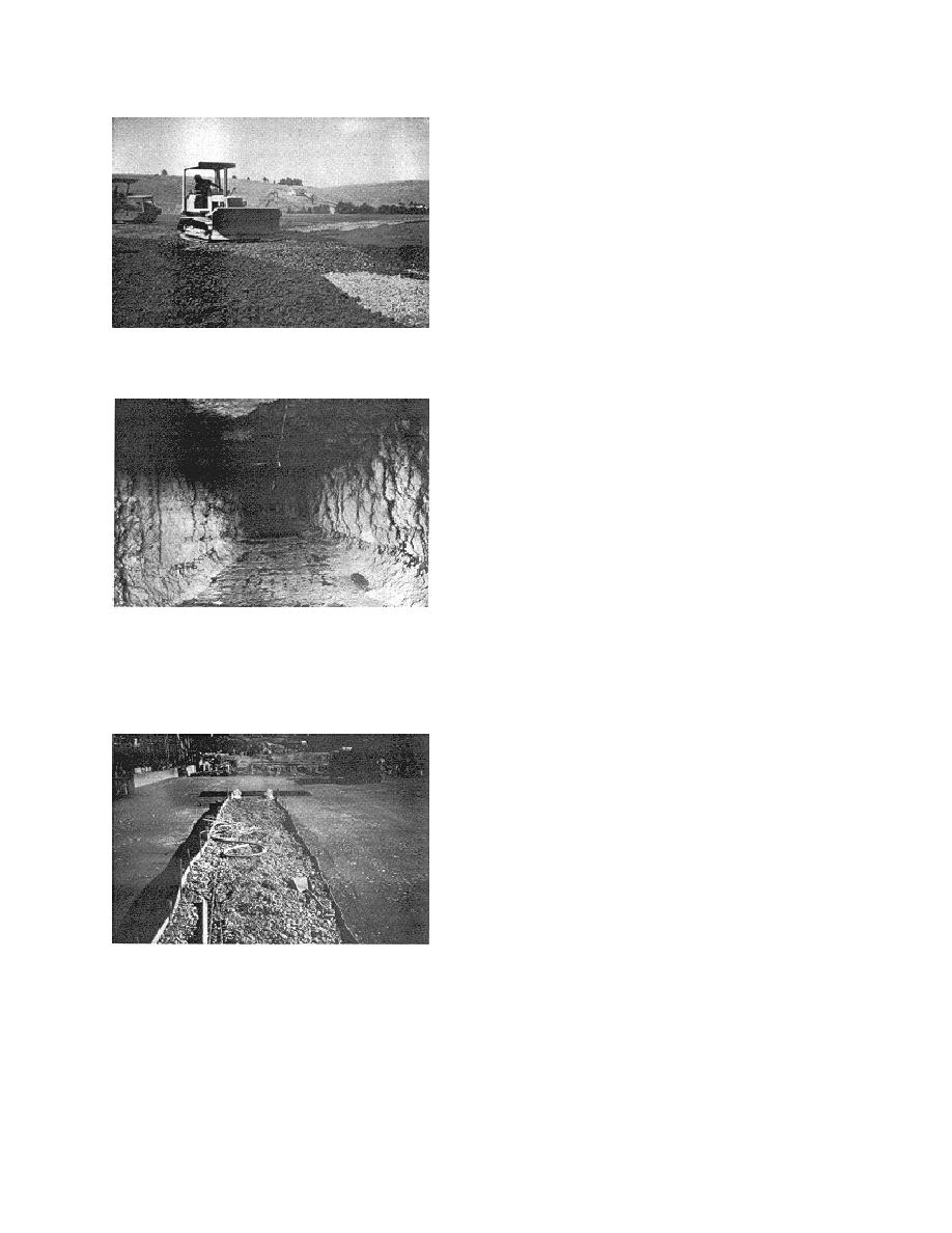
Figure 1-18. Gallery construction
required for top bars per ACI 318 in order to assure
full bond strength development. As an alternative,
anchorage reinforcement can be installed after RCC
placement by drilling and grouting. This procedure
is much more costly but does allow for more accu-
rate positioning of rebar and does ensure bar encap-
sulation and bond development.
(2) Structural reinforcement. RCC can and has
been placed with steel reinforcing. An example is
the spillway chute surfacing and apron for the
Toutle River Sediment Retention Dam. The RCC
for the spillway chute and apron was reinforced
with heavy welded wire mats. These mats were
provided in the RCC placement to: 1) prevent the
Figure 1-19.
After excavation of the
formation of wide cracks that might make the RCC
gravel/sand fill, protruding or loose RCC is
susceptible to deep abrasion erosion from ash-laden
removed. However, gallery walls are irregular
flood flows, 2) provide bending resistance to limit
and rough
cracking due to differential settlement, and 3) pro-
vide shear-friction resistance across cracks, to pre-
vent blocks of RCC, formed by perimeter cracking,
from being dislodged by flood waters. The welded
wire fabric is one innovative way of bringing the
strength and serviceability advantages of reinforced
structural concrete to an RCC placement. Another
means of improving RCC bending resistance might
be to place conventional reinforced concrete at the
extremities of an RCC placement where it is needed
to resist tensile bending stresses. This method
offers promise, but has not been used to date.
Reinforced RCC is shown in Figure 1-23.
7. Sampling and Testing Materials
Figure 1-20. Gallery construction using the
gravel/sand replacement method with wood
a. General. A comprehensive laboratory test-
plank forms to separate the RCC and
ing program is required to obtain the design mixture
gravel/sand fill to produce smoother, more
proportions for RCC strength and workability, to
uniform walls in the completed gallery
1-16


 Previous Page
