ETL 1110-2-355
31 Dec 93
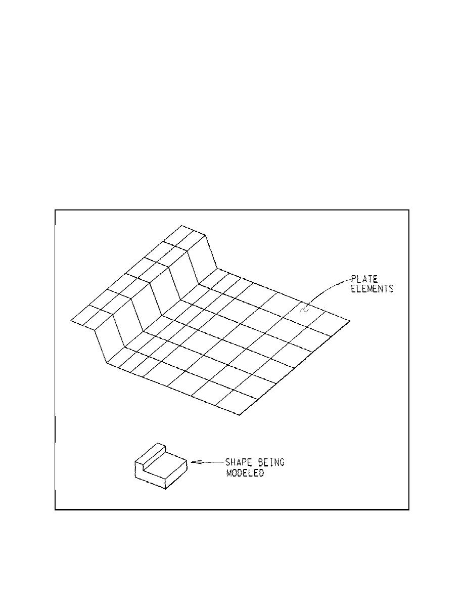
Figure A-10. A disadvantage to using this model is
of the slab. In using any of the methodologies, along
that the transition element is oriented unrealistically;
with engineering judgment, caution should be exer-
therefore, results near this row of elements will be
cised when evaluating the results. In addition, the
unreliable.
designer may wish to evaluate a variable thickness
slab using other methods, including multiple two-
(2) Stepped plate model. Again, elements are
dimensional strips through both transverse and longi-
tudinal sections.
placed at the centroids of the base slab as in the
sloped plate model and again require a transition
(1) Sloped plate model. The sloped plate model
between the two planes of elements. As seen in
uses shell elements located at the centroids of the
Figure A-11, a set of vertical beams connects the
base slab. Since the centroid of the thick portion of
planes of elements which must transmit the forces
the slab is at a different location than the thin portion
between the slab sections without introducing any
of the slab, a transition between the two planes of
unrealistic stiffness to the model. The beams may be
elements is needed. This is accomplished by con-
assigned arbitrary large values for the required sec-
necting the two planes of elements with the first row
tion properties.
of elements in the thick portion of the base as seen in
Figure A-10. Sloped plate model
A-26


 Previous Page
