ETL 1110-2-367
31 Mar 95
D-7.
Stage-Frequency for Interior Flood
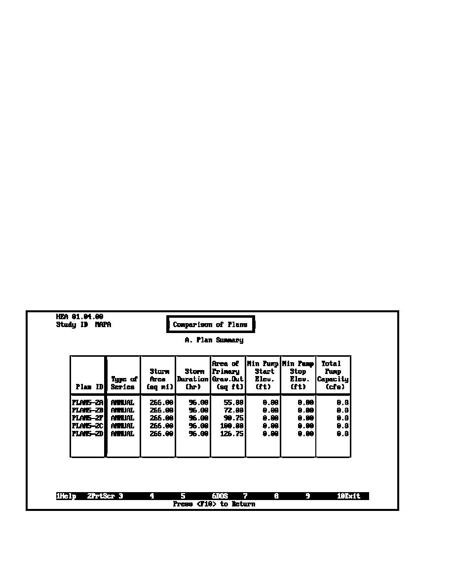
plans analyzed is shown in Figure D-22. Figure D-23 shows a
Damage Reduction Plans
comparison of the plan stage-frequency relationships.
c.
Determine stage-frequency for added pumping
a.
General. The objective of this task is to develop stage-
capacity.
frequency relationships that can be used to formulate a set of
flood damage reduction plans for each interior area. The
(1)
General. The analysis for Area 5 shows that
condition with the line-of-protection and the selected minimum
additional gravity outlet capacity is not effective, due to
gravity outlet in place becomes the without-project condition for
considerable coincidence between interior runoff and high
evaluating additional features, such as additional gravity outlets,
exterior stages. Residual damages may be significant, and
pumping stations, additional ponding area storage, and
pumps may be justified. The same steps described for
nonstructural measures.
evaluating additional gravity outlet capacity are appropriate for
evaluating added pumping capacity. Some differences in the
b.
Stage-frequency relationships for additional gravity
analysis are described below.
outlet capacity using data previously developed for the HEA
(2)
Base condition. The base condition for evaluating
with the minimum facility in place were defined. Only the
pumping capacity is with the minimum facility and, most likely,
gravity outlet data needed to be changed to define plans with a
the economic optimal gravity outlet configuration, in place.
range of outlet sizes. Four or five gravity outlet configurations
Several plans are evaluated against the base plan, each with an
(modules), with one or more gravity outlets in addition to the
incremental increase in pumping capacity. At the time of this
minimum facility outlet, were defined. Each module represented
writing the preliminary economic optimal gravity outlet was
an incremental increase in total outlet capacity. Several plans
selected as four 5- by 5-ft box culverts (Plan 5-C). HEA plans
that incorporated the gravity outlet modules were defined and
for Area 5 with the selected outlet and three different size
interior stage-frequency relationships were developed for each
pumping stations were defined and analyzed. The plan
plan. The HEA results were adopted to establish a final stage-
configurations are shown in Figure D-24 and the stage-
frequency relationship for each gravity outlet plan. These
frequency relationships are shown in Figure D-25. These
relationships will be used in the economic analysis to select an
relationships will be used to define the optimal pumping station
optimal plan. A plan summary for the four different Area 5
size for interior Area 5.
Figure D-22. Summary of plans for evaluating additional outlet capacity - HEA
D-18


 Previous Page
