ETL 1110-2-562
30 July 2004
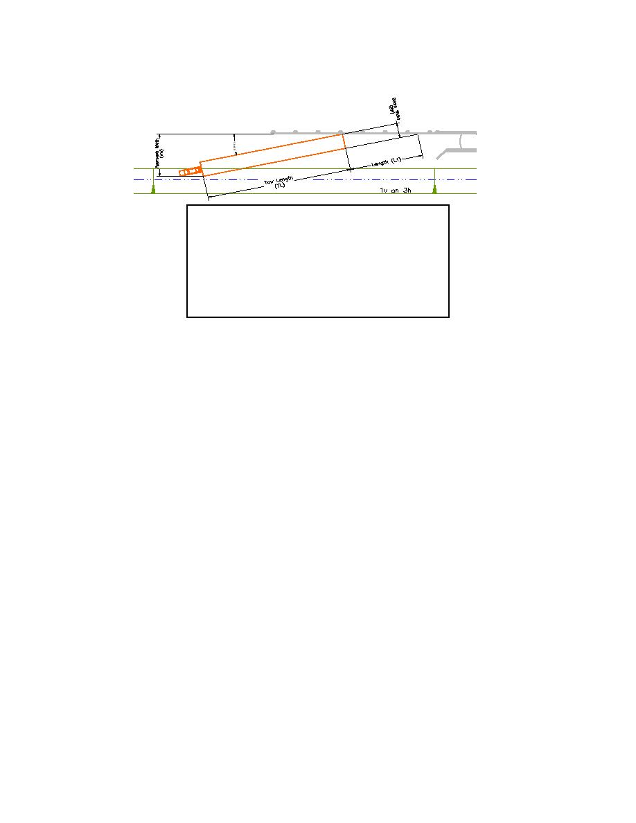
AW = sin (Θ)*(TL + L1)
where
L1 = BW / tan (Θ)
Θ = maximum approach angle
(12 to 15)
BW = width of tow
TL = length of tow
AW = sin (Θ)*(TL + (BW / tan (Θ))
Figure 1. Determining Approach Width (AW)
Park (2002) and Stockstill (2002) suggest that optimizing the ratio of the sum of the
total port area (ΣAports) in the guard wall to the sum of intercepted cross-sectional
area (ΣAxs) would balance the outdraft and draw toward the wall. Based on
laboratory experiments, the ratios of ΣAports / ΣAxs listed in Table 1 were determined
to provide acceptable navigation conditions for a single multi-cell, long span, and
floating guard walls with nominal lengths of 1200 ft and approach widths of 300 ft.
Note that the recommended ratio for the multi-cell guard wall is lower than those
observed with the long span and floating guard walls. This is due to the vane action
induced by the circular cells. That is, the cells in the multi-cell guard wall tend to
train the flow more normal to the wall.
Laboratory experiments also showed that, in some cases, improved guard wall
performance could be achieved by reducing the height of the ports in the downstream
one-fourth to one-third of the guard wall length. This is particularly helpful when
high velocities are encountered in the lock approach. By reducing the size of the
downstream ports, more flow is forced through the upstream ports. When sized
correctly, the flow along the wall will become more uniformly distributed.
A wider approach width of 550 ft. was evaluated with similar guard wall
configurations previously tested in the 300 ft. approach width. The intercepted cross-
sectional area, Axs, was increased by almost 200% while port openings remained
3


 Previous Page
