ETL 1110-2-563
30 Sep 04
(4) The design of a navigation lock should use different values of impact forces and return periods
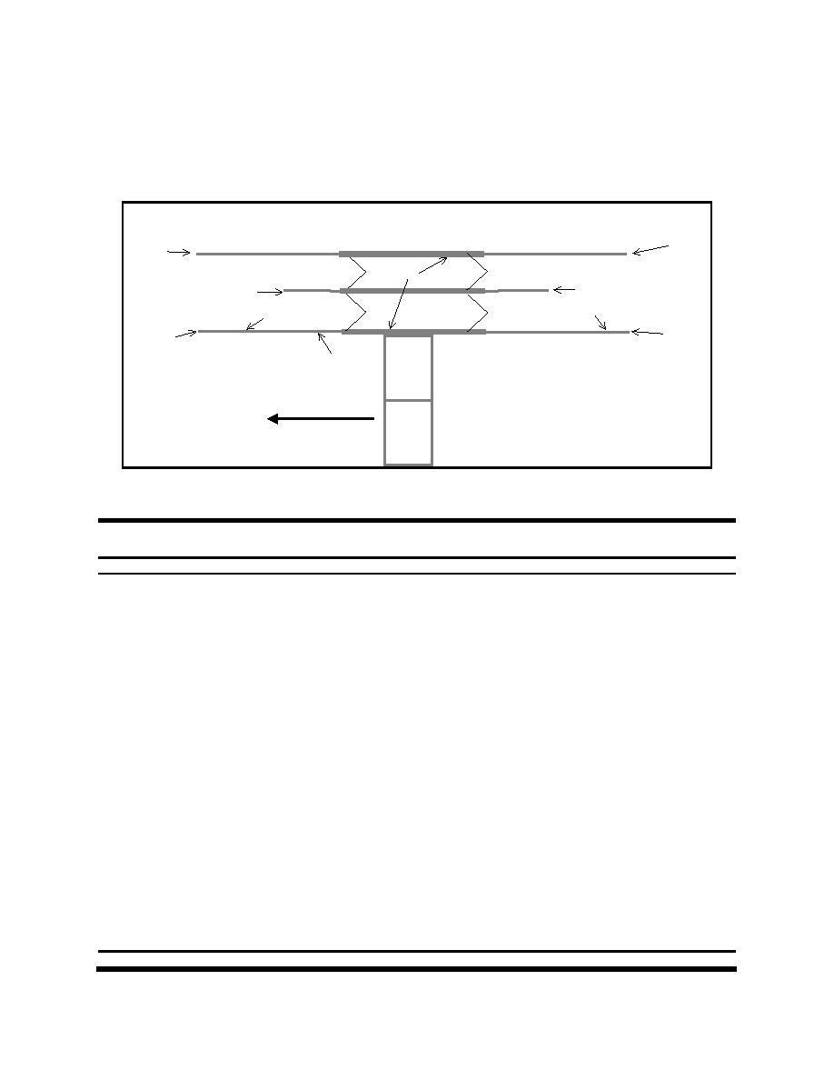
for the structural analysis of each wall section. Figure B-10 shows an example layout of a lock and the
location for the values of impact forces determined using the PBIA procedures defined previously.
Table B-5 shows an example of the impact location and loads to be used for preliminary design of a lock
structure.
Landside
Blower
Bupper
F
A
E
Clower
Cupper
F
A
Dupper
Dlower
F
A
G
Flow
Figure B-10. Examples of impact loads on lock structures (see Table B-5 for explanation of symbols)
Table B-5
Example of Preliminary 9-Barge Design Impact Forces and Locations
Symbol (Figure B-10)
Location
Event
Impact Load, kips
A
Lower protection cell/bullnose
Extreme
1,000
Blower
Lower land wall
Usual
150
Unusual
250
Extreme
350
Upper land wall
Bupper
Usual
300
Unusual
500
Extreme
700
Lower middle wall
Clower
Usual
100
Unusual
150
Extreme
250
Upper middle wall
Cupper
Usual
200
Unusual
300
Extreme
500
Lower river wall
Dlower
Usual
200
Unusual
300
Extreme
400
Upper river wall
Dupper
Usual
400
Unusual
600
Extreme
800
E
Chamber walls
Usual
100
Unusual
125
Extreme
150
F
Upper protection cell/bullnose
Extreme
2,000
G
Maintenance Impacts
Loads presented are for commercial barges. These design forces
on this portion of the wall should use values based on anticipated
operation and maintenance practice.
1
To convert kips to kilonewtons, multiply by 4.448.
B-14


 Previous Page
