ETL 1110-2-367
31 Mar 95
headwater versus tailwater with discharge as the matrix's
bends, contractions, expansions, entrance, and exit for the
internal elements to interpolate outlet discharge.
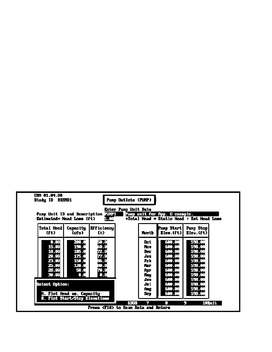
pumping unit. The total head represents the operating head at
various pumping outflow capacities. It is computed as the sum
(c) Gravity outlets are open whenever the interior water
of the head loss and static head (exterior elevation minus interior
elevation exceeds the exterior elevation by a user-specified
elevation). The final value of head is entered in the total head
minimum value (head). The outlet is assumed closed for all
column. It is the maximum head against which the pump can
other conditions. A different operation is performed if a gate
discharge water from the interior. If the maximum head is
closure value is specified. Gravity flows are then assumed to
exceeded, the pump is assumed to shut off.
cease when the exterior stage exceeds the gate closure elevation.
Up to five gravity outlets may be entered at the primary location
(c) The user may also specify pump start and stop elevations
and for each of the four secondary locations. Chapter 6 of the
on a monthly basis as shown in Figure 3-19. This flexibility is
HEC-IFH user's manual provides detailed descriptions of the
useful where seasonal operation requires different pumping and
gravity outlet data entry and analysis options.
interior ponding operation criteria such as for agricultural or
environmentally sensitive areas. On-off elevations are typically
(5) PUMP module.
constant throughout the year in urban areas. Chapter 7 of the
HEC-IFH user's manual provides a detailed description of the
(a) The PUMP module specifies pump characteristics used
PUMP module.
to determine the amount of water pumped from the interior area
during flood events. Up to ten different pumping units may be
(6) EXSTAGE module.
defined for an interior area. The station is assumed to be located
at the primary outlet.
(a) The exterior stage module defines the stage hydrograph
in the channel exterior to the line-of-protection. Exterior stage
(b) The pumping facilities are defined by a total head-
represents tailwater elevations that effect seepage and outflow
capacity-efficiency relationship, shown in Figure 3-19. It is
of the gravity outlet and pumping stations of the interior area.
normally determined from mechanical and/or electrical
For CSA, a continuous exterior stage hydrograph is required.
engineering analyses. For standard type pumps, the information
For HEA, exterior stage hydrographs are required for each event
may be obtained from the pump manufacturers. The head loss
analyzed. The magnitude of the exterior stages and their
represents the lump sum of all various losses due to friction,
coincidence with interior runoff/inflow affect outflow and,
Figure 3-19. Pump unit data entry screen for continuous simulation analyses
3-14


 Previous Page
