
ETL 1110-2-533
30 Sep 94
b.
Spillway control system.
(1) In a moderate to severe earthquake, it is
possible that all power will be lost at a project. In
that case, the water flowing through the turbines will
be shut off automatically. At many hydropower
plants the spillway gates would have to be opened
quickly to prevent the reservoir from overtopping the
dam. These spillway gates are operated by electrical,
motor-driven cables, gantry cranes, or with hydraulic
systems. Engine-driven backup power systems
should be provided to operate this system during an
emergency.
(2) The integrity of the spillway control system
Figure B-10. An unanchored heavy item of equip-
components should be evaluated. Of particular con-
ment can cause a pipe failure. An unanchored
cern is the power for motor-operated systems and
pump and sump used to operate the wicket gates
anchorage of hydraulic components.
can cause a pipe or pipe flange failure. Loss of
pressure would deactivate the hydraulic wicket
(3) The response time for opening the spillway
gate system
gates should be checked to ensure that it is adequate
if all turbines are shut down.
c.
Wicket gate governor systems.
(1) The wicket gates are usually operated by a
hydraulic governor system. The governor system
consists of a pump or pumps and oil sump, an oil
tank covered by high pressure air, hydraulic valves,
hydraulic actuators, piping connecting system compo-
nents, and electronic monitoring devices and control
circuits. When fully charged, the system can operate
the wicket gates about five times without using the
pump. The various elements of the control system
and the elements of the hydraulic system should be
evaluated.
(2) In general, piping systems are seismically
rugged and perform well if long, unsupported pipe
runs are avoided. Pipe failures are usually associated
with the relative motion between pipe anchor points,
for example, a pipe anchored to two different struc-
tures, or a pipe connected to a heavy, unanchored
object, such as a tank (Figures B-10 and B-11). Oil
tanks, which are often found in these systems, must
be securely anchored. When the incoming pipes are
rigid, it is desirable to design the piping system so
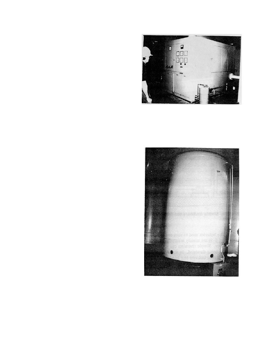
Figure B-11. An unanchored tank in the wicket
that tank piping connections are flexible to accommo-
gate hydraulic system. The unanchored tank in
date moderate tank movements. Another common
the wicket gate hydraulic system would cause the
piping failure is associated with a small diameter pipe
failure of the main piping system if the tank tips
that is relatively inflexible coming off of a large pipe
over, or break a smaller pipe if it moves slightly
that is flexible.
B-8

 Previous Page
