
ETL 1110-2-544
31 Jul 95
soil model were obtained from the interpretation of
3-3. Case History: Birch Dam
tests performed in the drained and undrained triaxial
a. Project description. Birch Dam, built across
tests, respectively. All time dependent stresses and
Birch Creek between 1974 and 1976, has a maximum
movements were computed indirectly since ISBILD is
height of 70 ft and a crest length of 3,200 ft. The
a statics program which does not account for
embankment was constructed across alluvial soil
consolidation. Separate finite element analyses were
deposits which vary in thickness from 10-ft near the
performed to model the construction sequence for both
abutments to a maximum of 37-ft near the center of
drained and undrained conditions. These are extreme
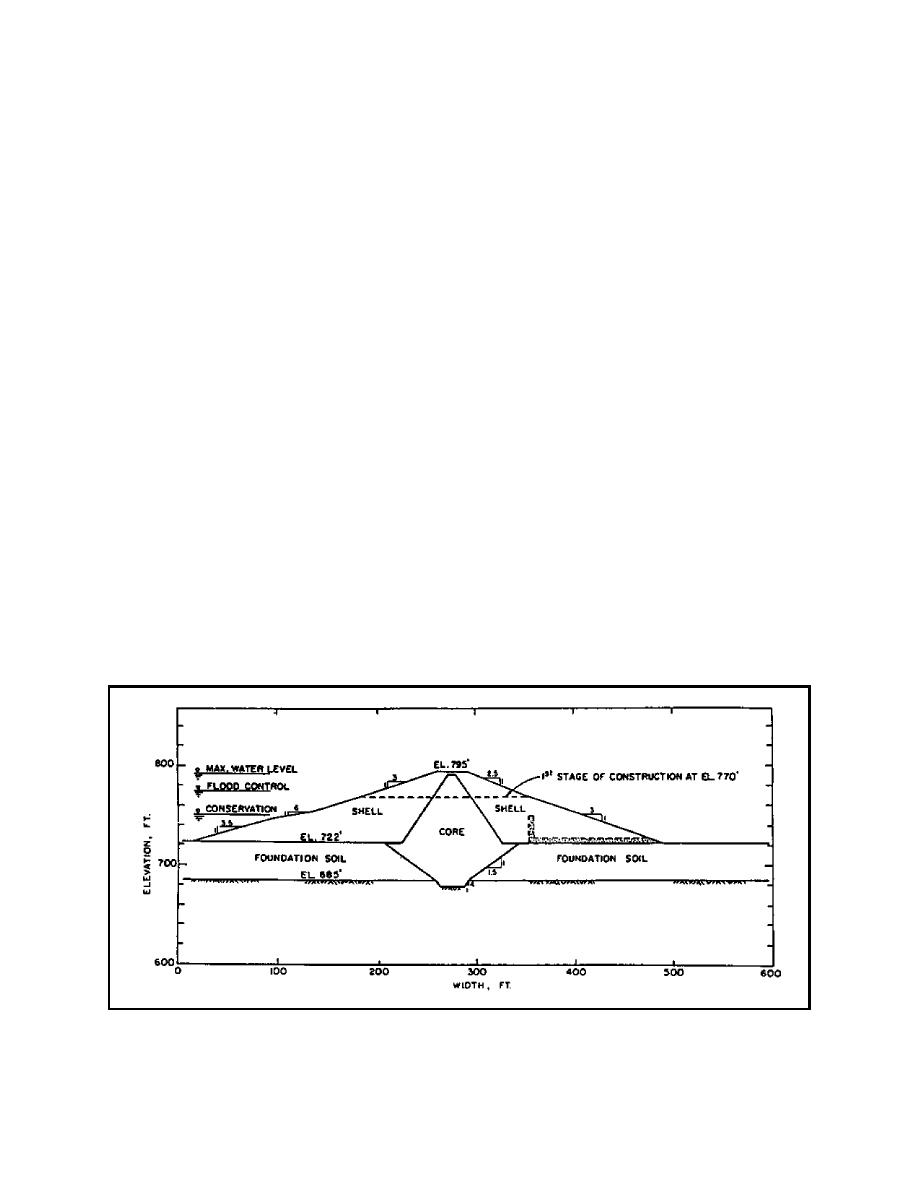
the valley. A cross-sectional view of the
conditions in which the analysis is carried out
embankment is shown in Figure 16. The foundation
assuming that there is no dissipation of pore pressure
was primarily composed of compressible silts and
at all times for the undrained case and complete
clays with numerous lenses of silty and clayey sands.
dissipation of porewater pressures for the drained case.
The core and cutoff trench contain materials which
In this study, the authors contrived a scheme based on
clas-
Terzaghi's theory of consolidation to weight the
sify as a CL (according to the Unified Soil
drained and undrained cases to determine the dis-
Classification System). The upstream and downstream
placements and stresses in the embankment at any
shells contain coarser and less plastic materials which
time.
clas-sify as ML's. The finite element analysis of Birch
Dam was reported by Soriano, Duncan, and Simon in
d. Mesh details. The mesh used for both the
1976.
drained and undrained analyses is shown in Figure 17.
Only half of the mesh upstream of the centerline was
modeled in the analysis due to the symmetrical
b. Purposes. The finite element study of Birch
geometry of the cross section. A full mesh was used
Dam was performed to predict the stresses and move-
to model the filling of the reservoir because of the
ments in the embankment and foundation during con-
asymmetry of the loading conditions. Seepage forces
struction, at the end of construction, and after filling
were determined from a seepage analysis and applied
of the reservoir. The finite element analysis of Birch Dam
as concentrated forces to the appropriate nodal points
was reported by Soriano et al. (1976).
in the full mesh. The resulting movements and
stresses were then calculated.
c. Material model, properties, and finite element
Code. The hyperbolic model as implemented into
e. Construction sequence. The construction
ISBILD (predecessor to FEADAM), was used for the
schedule is presented in Figure 18. Both the drained
analysis of Birch Dam. The parameters for the
Figure 16. Cross-sectional view of Birch Dam
A-17

 Previous Page
