
ETL 1110-2-563
30 Sep 04
(2) The previous USACE barge impact design methodology
for inland navigation structures is discussed in ETL 1110-2-338.
The response of the barges and wall is modeled as a two-degree-
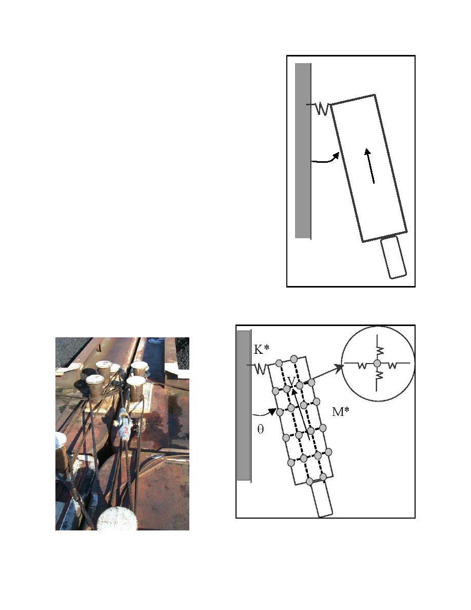
K
of-freedom (TDOF) system as shown in Figure B-2 where K is
the stiffness, M is the mass, V is velocity, and θ is the approach
angle. The input required to this TDOF model is the mass, size
(width and length), approach velocity, and angle of impact of the
barge train. The model was developed for both rigid and flexible
V
structures and was based on a constant pressure coefficient
developed by Minorsky (1959). This Minorsky model relates the
kinetic energy lost during impact to the damage sustained during
collisions of deep-draft vessels, and assumes that permanent
deformation and penetration will occur during crushing of the
θ
vessel hull.
M
(3) However, the model developed in ETL 1110-2-338 had
significant limitations. First, the existing TDOF model did not
account for the flexibility of the barge train during impact on a
navigation structure. This flexibility is caused by the lashings
(or wire ropes) that tie the barges together and is a mechanism for
absorption of energy within the mass of the barge train.
Figure B-3 shows an example of deck lashing for an internal
connection. An improved model from the TDOF is represented
by a Multi-Degree-of-Freedom (MDOF) system as shown in
Figure B-4 where K* is the equivalent stiffness, M* is the
Figure B-2. Two-Degree-of-Freedom
equivalent mass, V is the velocity, and θ is the approach angle of
barge train-wall system (Patev 1999)
the barge train.
Figure B-4. Multi-Degree-of-Freedom system (from
Patev 1999)
Figure B-3. Deck lashing (from Patev,
Barker, and Koestler 2003a)
B-2

 Previous Page
