ETL 1110-1-163
30 Jun 96
Geomembranes used in conjunction with slurry walls
(2) Applicability. In general, the advantages of
provide lower hydraulic conductivities for the com-
deep soil mixing are the minimal handling of contam-
pleted wall; however, the additional cost of the
inated soils during installation, and when compared to
geomembrane installation must be considered. It may
a vibratory beam wall, a thicker wall. Some concerns
with the technique are wall continuity, (due to vari-
be necessary to run compatibility tests between site
ances in column overlap), and ensuring that the key
contaminants and the proposed sheeting materials.
layer has been reached and penetrated.
SoilsawTM walls.
g.
f.
Geomembrane walls.
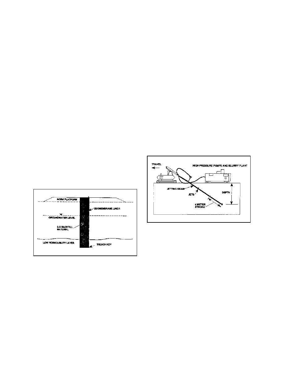
(1) Description. The SoilsawTM barrier system
(Figure 5) can form a vertical barrier wall which
(1) Description. One of the latest innovations
might be best described as a "mixed in place" wall.
from the geosynthetic industry is the use of geomem-
Various slurries or grouts may be used to mix with in
branes (Figure 4) made of high density polyethylene
situ soils by means of a jetting pipe which has grout
(HDPE) sheeting for vertical barrier walls. Geomem-
jets located at regular intervals along the bottom of
branes may be installed directly into softer soils with
a vibratory hammer, or for deeper installations, the
the pipe. The jetting pipe is attached to a mechanical
geomembranes are used to complement either S-B or
crawler machine which is able to reciprocate the pipe
C-B walls. When placed in a pre-excavated trench,
along its length through a stroke equal to the spacing
the geomembrane panels may line one side of the
of the grouting jets. The jetting pipe is supplied with
high pressure (3,500 N/cm2 (5,000 psi)) slurry from
trench, installed either with a vibratory hammer or
mounted on a steel frame and inserted into the trench.
separate mixing and pumping equipment.
Another technique is to line both sides and the bot-
tom of the trench by draping the geomembrane panels
into the trench by using ballast material. The geo-
membrane panels are typically 1.5 to 3 mm (60 to
120 mils) thick, with each sheet interlocking to the
preceding panel.
Figure 5. SoilsawTM barrier system
When the system is operating, the soil under the
jetting pipe is liquefied along the entire length of the
jetting pipe, and the beam sinks into the ground under
its own weight. As the pipe reaches its working
depth (approximately 45 deg), the crawler begins to
Figure 4. Slurry trench with geomembrane liner
travel at a rate which enables the jetting beam to
Depending on soil conditions, walls may be con-
maintain the proper depth. Present equipment is
structed to a depth of 30 m (100 ft). Interlocks are
capable of forming a cutoff wall which is approxi-
sealed from leakage by the installation of a joint seal.
mately 300 mm (12 in.) wide.
(2) Applicability. Currently, the SoilsawTM
(2) Applicability. The use of geomembranes as
a vertical barrier wall provides an excellent barrier to
method is in the research and development phase.
groundwater movement. Geomembranes installed as
While not yet commercially available, it is planned to
be used commercially in the future. The SoilsawTM
shallow sheet piles are not able to penetrate particu-
larly stiff or rocky soils and, thus, are very dependent
method is best suited for soils which are fairly uni-
on site soil conditions and are limited in depth.
form with occasional rocks and debris present. Small
B-11


 Previous Page
