ETL 1110-2-343
31 May 93
removed and remixed with fresh RCC and respread
by the dozers. Additional layers of RCC are spread
until the final lift thickness is achieved and final
compaction rolling begins. Final compaction is
accomplished using self-propelled single-or double-
drum vibratory roller-compactors, rolled with suffi-
cient passes until optimum compaction is achieved.
The interval between mixing and final compaction
should be kept to a minimum, generally less than
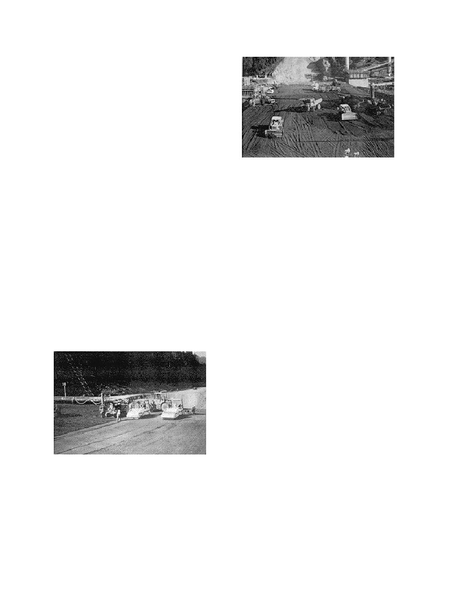
45 min (Reference 12c). Figure 1-5 shows RCC
being compacted by vibratory roller. Most of the
compactive effort is initially provided by dozer
action. Final compaction is accomplished by vibra-
Figure 1-6. RCC placement operation
tory rollers. Density requirements will normally be
established during test fill placements, and at the
initial start of RCC placement, and will be based on
and compaction equipment. Lift joints or horizontal
the evaluation of density test results and visual
construction joints are formed at the interface be-
observations. After final rolling, the compacted
tween successive RCC lifts. The total number of
RCC surface must be kept clean and continuously
lift joints in an RCC structure is determined by the
moist until placement of the next lift. Figure 1-6
thickness of each RCC lift and the overall height of
shows an RCC placement operation. RCC is depos-
the structure. Tensile and shear strength at lift
ited on the previous lift that has been covered with
joints are less than in the parent RCC. Segregation
a thin layer of high slump mortar bedding or con-
of the RCC and lack of bond at the lift joints can
ventional concrete. The mortar bedding assures that
result in increased seepage and potentially high
there is adequate paste at the lift surface boundary
uplift pressures at joints exposed to hydrostatic
to provide bond and to reduce lift surface materials,
pressure. Final structural design and stability analy-
and partially compact the RCC prior to final com-
sis for RCC structures should be based on joint
strength determined from laboratory tests made on
paction by the vibratory roller. Care must be taken
cast specimens and cores from test placement
by the dozer operator, as well as other equipment
sections.
operators, so as not to damage the surface of the
previous RCC lift and to prevent unnecessary
d. Horizontal lift joint treatment.
segregation.
(1) The type and degree of lift joint surface
treatment used is dependent on the required bond
and watertightness needed for the structure. Stan-
dard lift joint treatments consist of simple con-
tinuous moist curing, cleaning contaminated areas
by washing and vacuuming, and application of a
bedding mortar or bedding concrete immediately
prior to placing the next RCC lift. For RCC lifts
where bonding and watertightness are not critical,
lift joint treatment may consist of simple continuous
moist curing only. However, the elimination of
bedding mortar will require the submittal of sup-
porting backup data and the approval of CECW-E.
Figure 1-5. Compaction by vibratory roller
For RCC hydraulic structures where bonding and
watertightness are important, a bedding mix shall be
c. Lift joints (Horizontal Construction Joints).
applied to all lift joint surfaces. Insulation and
RCC lifts may range in thickness from 6 to 24 in.,
temperature monitoring may be required in cold
depending on the placement size, production capac-
weather to ensure that exposed surfaces are not
ity of the concrete batch plant, mixture proportions,
1-6


 Previous Page
