ETL 1110-2-343
31 May 93
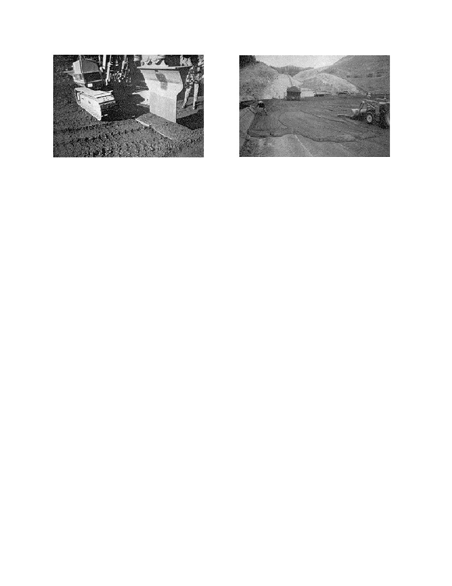
Figure 1-7. Contraction joint installation
Figure 1-8. Application of mortar bedding
g. Bedding. Mortar or concrete bedding is
may be used to protect the RCC from environment
required on all RCC cold joints and is required for
exposure or to enhance the appearance of the
use on all lift joint surface areas of hydraulic struc-
structure.
tures in order to maximize bond and water tight-
ness. Bedding mixes are designed for maximum
(2) At Elk Creek Dam, the upstream facing
workability with 7- to 9 in. slump and a design
system consisted of a 3- to 4-ft-wide zone of air-
strength that at minimum exceeds the strength of
entrained conventional concrete placed concurrently
the parent RCC. Bedding concrete is designed with
with the RCC lifts. The conventional concrete was
3/4-in. or less nominal maximum-size aggregate
consolidated with internal vibrators and tied to the
(NMSA) and bedding mortar with 3/8-in. NMSA or
RCC with reinforcing steel at the lift joints. This
less. Normally, bedding mortar is spread in a 1/4-
system required formwork at the upstream face of
to 1/2-in. thick layer and bedding concrete in a
the dam to contain the conventional concrete, but
1/2- to 1-in. thick layer on the RCC surface. Bed-
resulted in superior protection of the RCC as well
ding is placed immediately prior to the next RCC
as a conventional concrete appearance to the struc-
lift on the underlying RCC surface. Figure 1-8
ture. Figures 1-11, 1-12, and 1-13 show the stages
shows mortar bedding being applied and Figure 1-9
in the placement of a conventional concrete facing.
shows foundation treatment details. Bond and
Conventional concrete is placed against the form,
watertightness are improved by spreading a thin
followed by RCC. The conventional concrete and
layer of high-slump mortar or concrete as a bedding
conventional concrete RCC interface is consolidated
on previously compacted RCC surfaces and on
with immersion-type vibrators. Final consolidation
foundation rock surfaces to receive RCC
of the RCC at the conventional concrete RCC inter-
placements. The extent and type of foundation
face is accomplished with the vibratory roller.
treatment used will vary considerably depending on
job conditions. Typical foundation treatment details
(3) Precast concrete panels were used at the
are shown for (a) foundation slopes of 3 horizontal
upstream face of the Willow Creek Dam. The
to 1 vertical or less, and (b) slopes steeper than 3
panels were fitted with tie-back straps, that, when
horizontal to 1 vertical.
embedded in the RCC at the lift joint, would hold
the panels in position during consolidation of the
h. Facing systems.
RCC and provide the vertical formwork required at
the upstream face. The panels provided a pleasing
(1) A facing system may be used to cover the
architectural appearance to the dam at the upstream
exposed vertical or sloping edges of an RCC
face, but did not limit water seepage through the
structure in order to protect the RCC from the
RCC. It is important to note that uncontrolled
effects of freezing and thawing, to help minimize
water seepage through the precast concrete panel
seepage through the RCC, or simply to enhance the
facing system may allow very high hydrostatic
appearance of the exposed RCC. Facing system
pressures to develop during rapid drawdown of a
details are shown in Figure 1-10. A facing system
reservoir, resulting in possible failure of the facing
1-8


 Previous Page
