ETL 1110-2-344
31 Dec 93
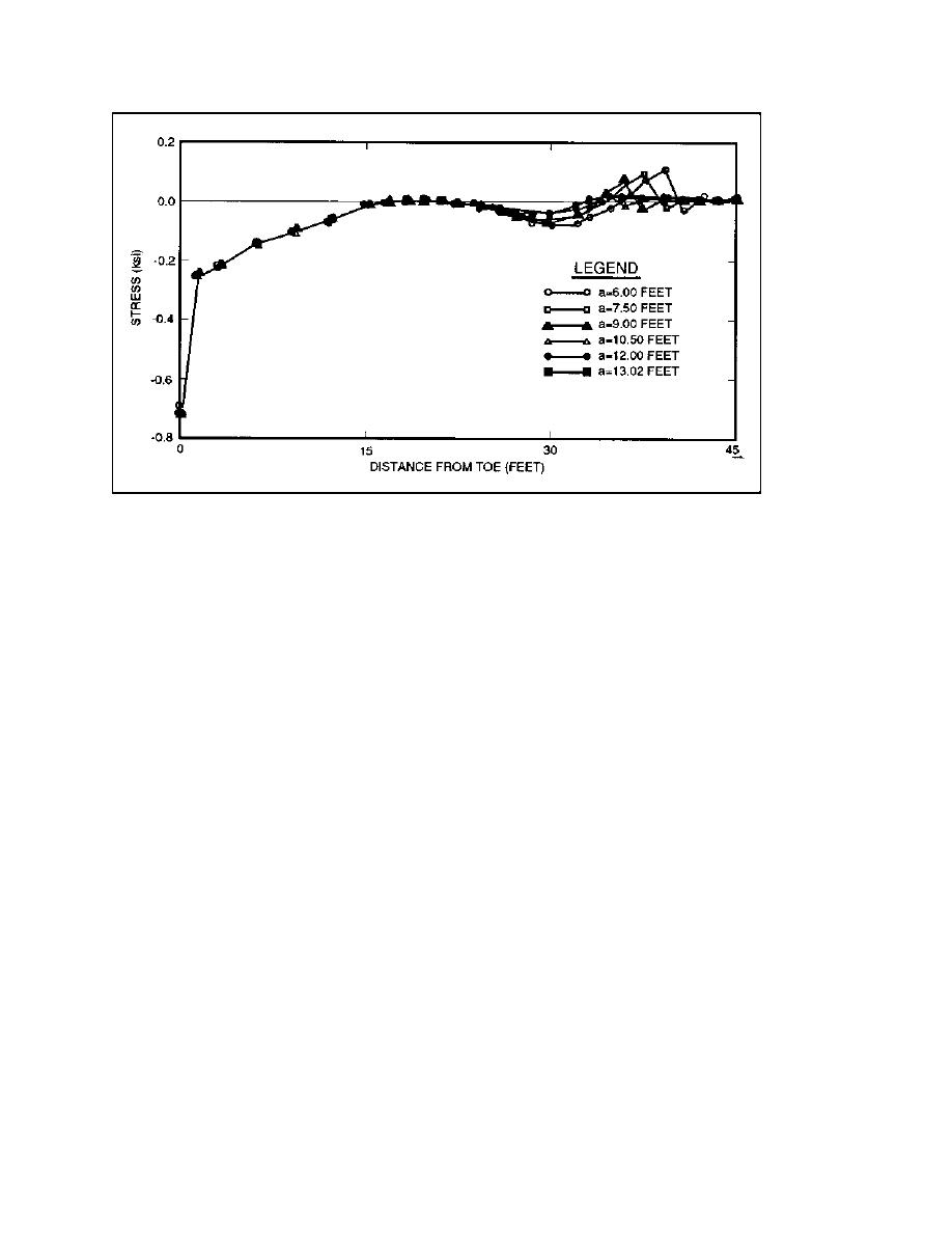
Figure A-10. Normal stress profiles at the base of the monolith
performed to determine the line of action for the
(b) The normal stress profiles along the base of
resultant forces from the two methods of analysis.
the monolith for the final crack lengths predicted by
The line of action for the resultant force from the
both the finite element analysis and the traditional
finite element analysis was 7.60 ft to the right of
method of analysis are shown in Figure A-11. The
the toe as opposed to 7.29 ft from the traditional
effective stress is plotted as a function of distance
analysis technique. Confidence in the finite element
along the base of the monolith (with the toe located
analysis is provided since the results show a good
at zero) and the negative sign on the stresses indi-
correlation between the two methods of analysis.
cates compression. The stress computed from the
finite element analysis was integrated along the base
(5) Shear stress profiles. The shear stress pro-
using the Trapezoidal rule to determine the resultant
file along the base of the monolith for a crack
force in the vertical direction. In order to assess the
length of 13.02 ft is shown in Figure A-12. The
accuracy of the finite element analysis, the resultant
integrated stress was computed to determine the
force was also computed for a crack length of
resultant force in the horizontal direction resulting
13.02 ft using the assumed stress distribution of the
in a value of 247.82 kips. Comparison to
traditional analysis technique. The crack length of
249.78 kips from the traditional method of analysis
13.02 ft was used in this computation rather than
shows a good correlation.
the predicted crack length of 23.13 ft because the
uplift forces are a function of the crack length and
(6) Vertical displacement profiles. The verti-
any other crack length would result in nonequiva-
cal displacement profiles along the base of the
lent force systems. A crack length of 13.02 ft
monolith for crack lengths of 6.0 to 13.02 ft are
yields a tensile stress at the crack tip using the
shown in Figure A-13. The vertical displacement
traditional analysis technique. The tensile stresses
were included in calculation of resultant forces
profiles are virtually identical for distances along
because this comparison is between two equivalent
the base of the monolith up to 20.0 ft. Beyond
force systems, not systems with equivalent crack
20.0 ft, the vertical displacement profiles diverge.
lengths. The resultant force from the finite element
The explanation for this phenomenon follows the
analysis was 416.64 kips/ft (kips per foot width) as
same line of reasoning as that for the behavior of
opposed to 414.37 kips/ft from the traditional analy-
the normal stresses along the base of the monolith,
in which the culvert near the interface between
sis technique. Similar computations were also
A-12


 Previous Page
