ETL 1110-2-344
31 Dec 93
Table A-2
Summary of Finite Element Analyses
KI
KII
∆Hcrest
a
CMOD
ksi .
√in
ksi√ .
in
ft
in.
in.
6.00
0.868
0.489
0.0111
-0.0806
7.50
0.743
0.483
0.0127
-0.0847
9.00
0.581
0.492
0.0140
-0.0881
10.50
0.387
0.521
0.0150
-0.0908
12.00
0.162
0.582
0.0155
-0.0924
13.02
0.000
0.643
0.0154
-0.0925
13.50
-0.083
0.678
0.0153
-0.0924
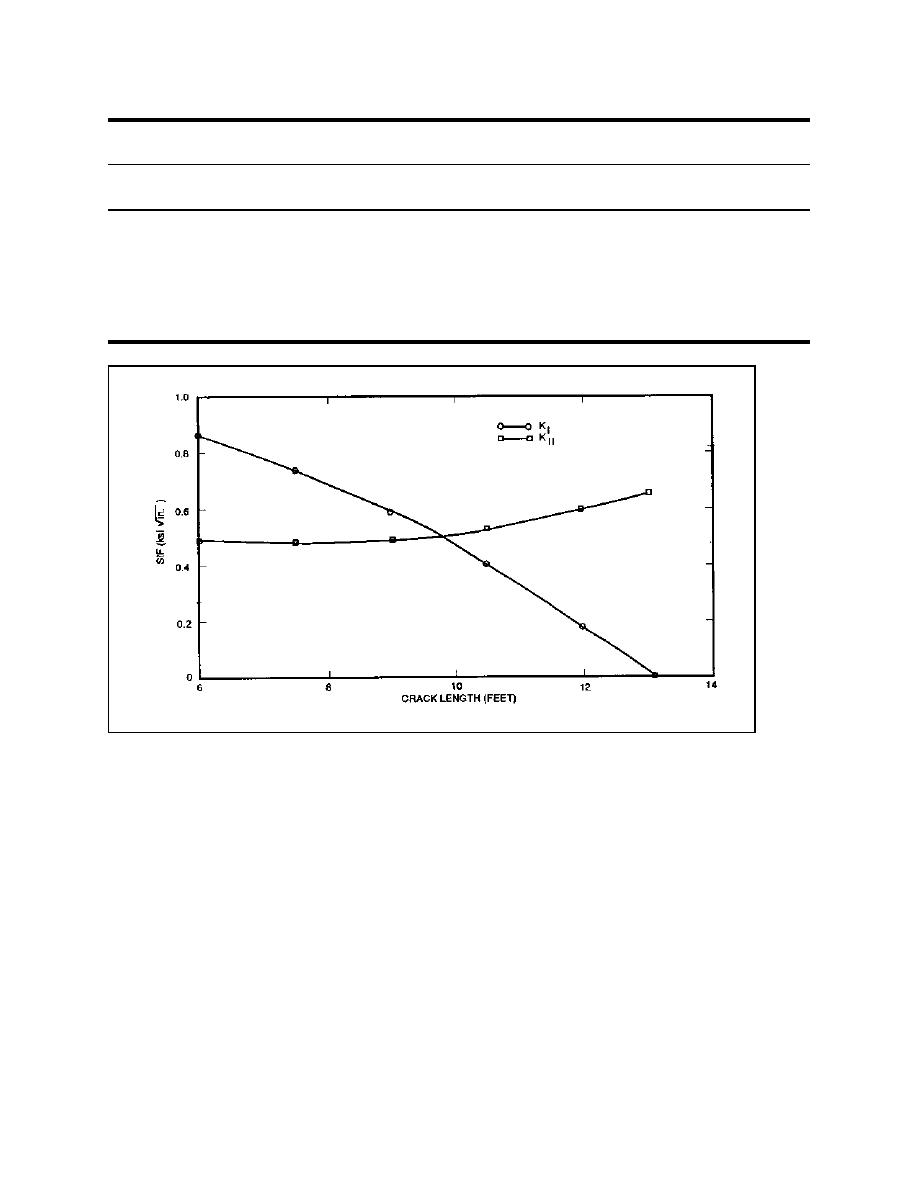
Figure A-8. KI and KII versus crack length for the monolith
these analyses, KI decreases with increasing crack
length because the gravity forces acting to close
increased would constitute an unstable fracture
crack become more dominant. Figure A-8 shows
that the value of KII is relatively constant for crack
geometry. For a stable fracture geometry in equilib-
rium, the loading must be increased in order for the
lengths between 6.0 and 9.0 ft, but increases with
crack to propagate and propagation will cease when
crack length beyond 9.0 ft. If KII is of sufficient
a new equilibrium configuration is reached. An
magnitude, the crack direction may change. When
unstable fracture geometry leads to a catastrophic
significant shear stress (related to KII) is combined
failure unless the loading somehow changes to
with the normal stress, the direction of maximum
create a stable fracture geometry once a crack
tension stress changes. For a competent material
begins to propagate. Because this is a stable frac-
(homogeneous and defect free), the direction of the
ture geometry, the horizontal and vertical uplift
crack will propagate perpendicular to the direction
forces acting to open the crack and the vertical
of greatest tension. For materials that are not
forces acting to close the crack reach an equilibrium
homogeneous and defect free, the crack will propa-
configuration, and crack propagation ceases. For
gate where a much lower KIc value exists or where
A-10


 Previous Page
