
ETL 1110-2-344
31 Dec 93
to lower KIc) and the mesh is better able to capture
there is a nearby pre-existing crack. For the Locks
27 monolith, data on the exact condition of the
them.
interface bond and foundation does not exist. If it
is assumed that the interface bond is perfect and the
(4) Normal stress profiles.
monolith and foundation materials are homogeneous
and defect free, the crack may curve away from the
(a) The normal stress (effective stress) profiles
interface, as the crack length increases beyond
along the base of the monolith for crack lengths of
9.0 ft.
6.0 to 13.02 ft are shown in Figure A-10. The
normal stress profiles are virtually identical for
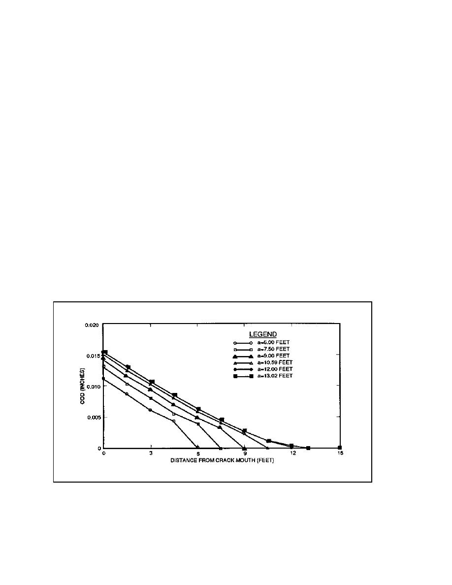
(3) Crack opening displacement profiles. The
distances along the base of the monolith up to
crack opening displacement (COD) profiles for
25.0 ft. Beyond 25.0 ft, the normal stress profiles
assumed crack lengths of 6.0 to 13.02 ft are shown
diverge. This lack of sensitivity to the crack length
in Figure A-9. The COD profiles for crack lengths
in the normal stresses at less than 25.0 ft is the
of 6.0 through 10.5 ft exhibit noticeable kinks near
result of the relatively large culvert in close proxim-
the crack tip which are not evident for longer crack
ity to the interface between the monolith and the
lengths. This effect is a function of the coarseness
foundation. There is only 8.0 ft between the bottom
of the mesh. As described, these results represent
of the culvert and the top of the foundation and the
cases where KIc = KI of Table A-2. For shorter
width of the culvert is almost one third that of the
entire monolith. The portion of the monolith under
crack lengths KIc would be larger; therefore, higher
the culvert lacks sufficient stiffness to transfer verti-
tensile stresses can develop at the uncracked region
cal stresses, effectively isolating the right side of
near the crack tip causing higher displacement
the monolith from the left side near the base. In
gradients. The mesh is too coarse to capture the
order to further determine the effect of the culvert,
high displacement gradients evident for shorter
an additional series of analyses was performed in
crack lengths; therefore, some distortion of the
which the culvert was not considered. The results
plotted displacements occurs in the region near the
of these analyses are summarized in Appendix B.
crack tip. As the crack length increases, the dis-
placement gradients near the crack tip decrease (due
Figure A-9. COD profiles for cracks at the base of monolith
A-11

 Previous Page
