
ETL 1110-2-533
30 Sep 94
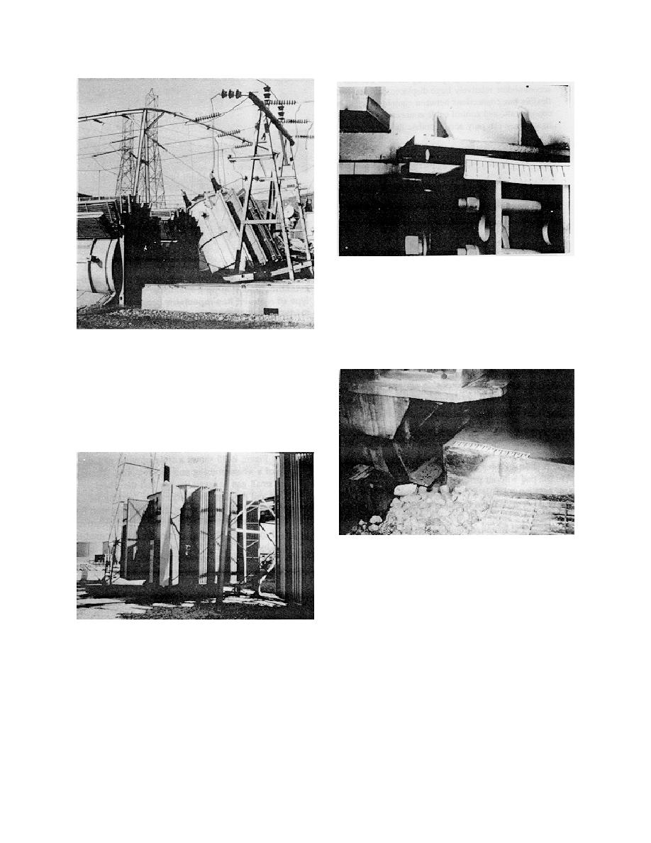
Figure B-24. Connection between step-up trans-
former and its carriage. The transformer carriage
is attached to the transformer at four locations,
each with two 1/2-in. bolts. If the carriage is not
adequately anchored, it may not be able to restrain
the transformer
Figure B-22. Failure of rail-mounted transformers
restrained by chocks. Five of the six single-phase
transformers fell from their supports, damaging
radiators, bushings, and the bus support structure.
Chocks clamped to the rails could not restrain the
transformers. Restoration is lengthy and expen-
sive. Note that the carriages on the 2nd and 3rd
transformers separated from their transformers
Figure B-25. Wheel restraint detail
The advantages of this method of attachment are that
no failures have been observed with well-designed
embedments, and transformers are rigidly held to the
foundation pad so that lift-off and subsequent impact
are avoided. Impacts introduce large accelerations
Figure B-23. Transformer restrained to rails. Over-
that can damage porcelain and bushing seals, and
all view of rail-mounted transformer which is
subject internal components to large forces. Another
restrained by large chocks and concrete keys
advantage of embedments is that problems with pre-
under the carriage. Note that the rails are mounted
positioning cast-in-place anchor bolts are eliminated.
to a slab at grade; however, the transformer has
Also, should the transformer need to be changed, and
no positive vertical restraint. Since the unit is not
oversize embedments were used in the initial design,
mounted on an elevated pedestal, it is less likely to
welds on the original transformer can be burnt off
fall over
B-16

 Previous Page
