
ETL 1110-2-533
30 Sep 94
(m) Transformer coolers, depending on their
and new equipment installed without modifying the
design, are vulnerable to oil leaks. Large coolers that
foundation pad.
are manifold-mounted are the most vulnerable. Typi-
cally, the upper structural support of the cooler is the
(k) The thickness of the embedment must be
adequate so that welds will not tear out of the mate-
penetration through the transformer case
rial and that loads transferred through the weld can be
(Figure B-27).
distributed to several of the bolts or hooks that trans-
fer the load to the concrete. It is desirable that the
embedment extend beyond the weld so that good load
transfer is made to the concrete. Embedment capaci-
ties should be based on headed studs or hooks and
not on bonding between the embedment plate and the
concrete. There should be adequate edge distance
between the embedment, and the pad boundary and
the placement of rebar between the pad edge and the
embedment should be considered.
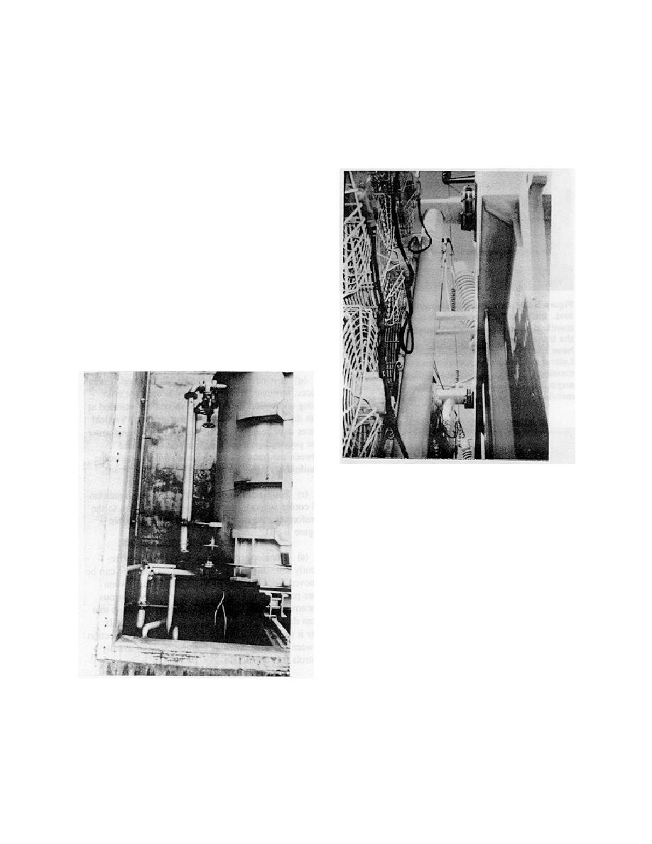
(l) Some step-up transformers at dams are water-
cooled rather than air-cooled. Movement of the
transformer can cause the failure to piping connec-
tions associated with the cooling system
(Figure B-26).
Figure B-27. Upper cooler support and trans-
former penetration. A large manifold-mounted
cooler is supported by the pipe that also serves as
the penetration to the transformer case. Lateral
forces can cause large moments on the flange and
oil leaks
(n) Transformers at a dam are vulnerable to oil
cooler leaks. Oil coolers with or without inadequate
vertical and horizontal bracing have developed leaks
at the flange connecting the coolers to the transformer
body (Figure B-28).
(o) When the lower penetration through the
transformer case serves as the primary support, it also
has a tendency to develop leaks (Figure B-29).
Figure B-26. Piping connections of water-cooled
transformers. Relatively rigid piping connections
(p) Coolers which are individually connected to
in water-cooled, chock-restrained transformers are
the transformer by their own penetrations have not
one of the main restraints to transformer motion.
developed leaks (Figure B-30).
Relatively small movement could cause pipe
flanges to leak
B-17

 Previous Page
