
ETL 1110-2-544
31 Jul 95
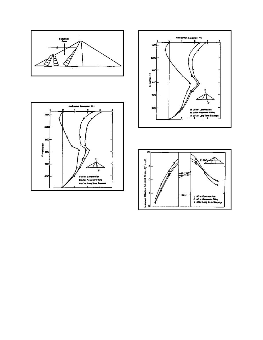
Figure 27. Treatment of upstream shell during
reservoir filling
Figure 29. Horizontal movements for "soft" core
FE analysis
Figure 28. Horizontal movements for "stiff" core
FE analysis
settlement rather than an uplift movement. The
Figure 30. Maximum principal stress for "stiff"
maximum and minimum principal stresses in the
core analysis
embankment for the "stiff" core case are shown in
Figures 30 and 31, respectively. For both cases, the
maximum and minimum principal effective stresses
These stresses were compared with the long-term
in the upstream shell decreased due to the effect of
stresses computed using the CON2D model in Figure
submergence. The maximum principal effective
32. The results show that the stresses are nearly the
stress in the downstream shell decreased a small
same for this case. Overall, the movements in the
amount, and the minimum effective principal stress
embankment were considered small for the range of
increased during consolidation and the development
compaction conditions considered in the analysis. It
of long-term seepage in the core. As part of
was speculated that the movements would have been
another finite element calculation, the long-term
larger had the core been treated as a wetter and softer
stresses were calculated using the hyperbolic
material. Additionally, the difference between the
constitutive model under the assumption that the
long-term stresses computed with the hyperbolic
construction was slow enough so as not to induce
model and the consolidation model might also have
excess porewater pressures during the placement of
been greater for the wetter and softer core.
fill.
A-24

 Previous Page
