ETL 1110-2-544
31 Jul 95
(3) Field tests. Permeability can be estimated
sand, approximately 100 ft deep. Below this sand
from field pump tests and falling head tests performed
layer is hard tertiary clay. A channel was cut from the
in boreholes.
Mississippi River through the mainline levee to divert
flow to the powerplant. An exit channel leads flow
b. Documented reference. Engineer Manual EM
away to auxiliary overflow channels. The entire site is
1110-2-1901 entitled "Seepage Analysis and Control
surrounded by a levee system which ties into the
for Dams" contains more detailed information on the
mainline levee and the natural levee and backswamp
methods for determining the coefficient of
deposits.
permeability.
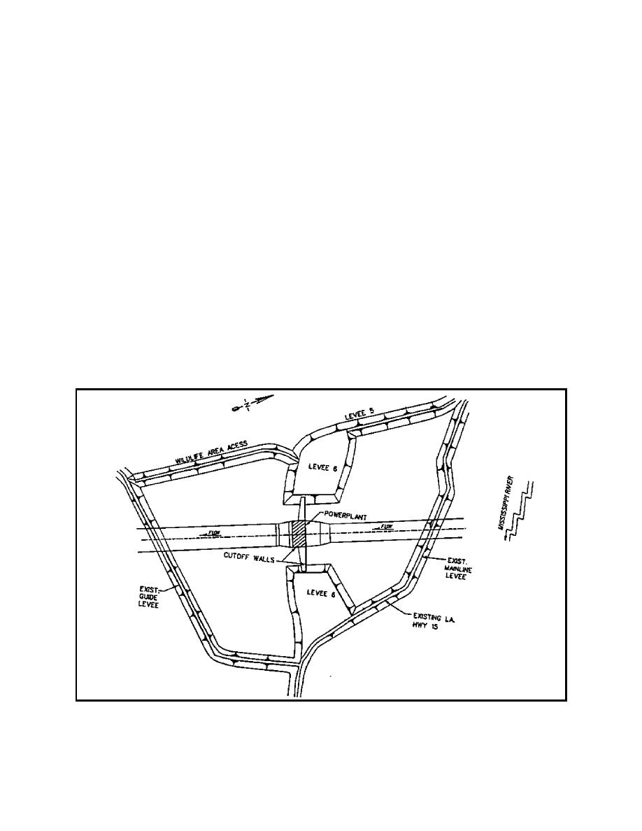
b. Purpose of analysis. As shown in Figure 34,
the powerplant receives flow from the Mississippi
River through a diversion channel and could
4-4. Case History: S. A. Murray Hydroelectric
experience differential hydraulic heads up to 26 ft from
Plant
project flood conditions and 41 ft under extreme
a. Project description. A 2-D plan view
conditions. These heads cause seepage to occur under
seepage analysis of the S. A. Murray, Jr. Hydroelectric
the structure and subject it to uplift pressures. Seepage
Station was reported by Knowles (1992). The power
control measures include concrete cutoff walls and a
plant is adjacent to the
drainage system. These cutoff walls under the
Mississippi River just upstream from the Old River
structure extend through the sand layer to the tertiary
Control Structure.
deposits. The analysis was performed to determine the
seepage and associated uplift pressure beneath the
Plan and cross-sectional views of the site are shown in
powerplant and other structural features (e.g. concrete
Figures 34 and 35. The powerplant is founded in a
channel linings) and to study the effect of the cutoff
medium to very dense layer of fine to medium
walls on the seepage.
Figure 34. Plan view of S. A. Murray Hydroelectric Plant
A-27


 Previous Page
