Home
Download PDF
Order CD-ROM
Order in Print
Home
>
USACE Technical Letters - index
>
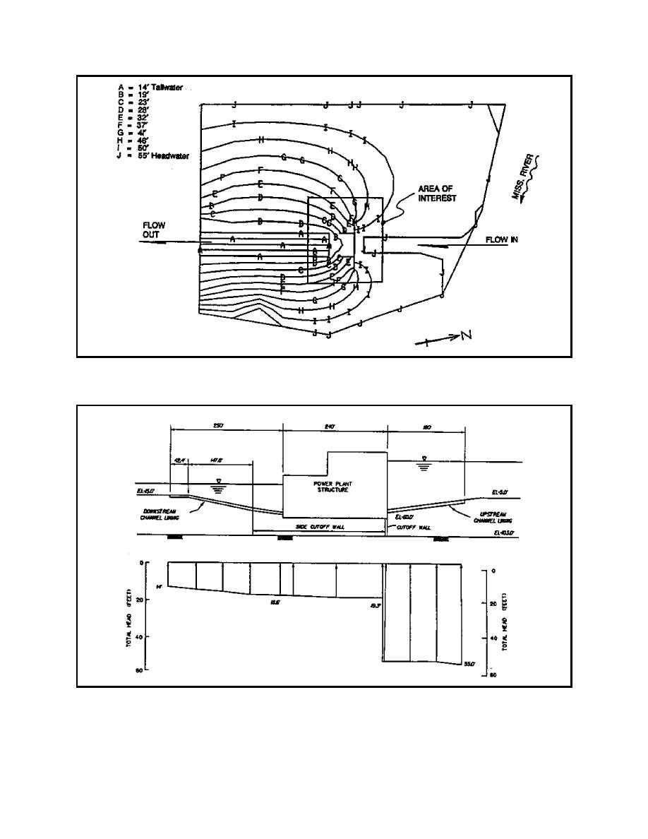
> Figure 38. Total head contours with cutoff wall at a permeability of 2 10-6 ft/min
Figure 36. Grid generated for plan view model of S. A. Murray Hydroelectric Plant
Figure 40. Uplift at centerline of powerplant and channel linings for a range of cutoff wall permeabilities
ETL 1110-2-544
Page Navigation
26
27
28
29
30
31
32
33
34
35
36
ETL
1110-2-544
31
Jul
95
Figure
38.
Total
head
contours
with
cutoff
wall
at a
permeability
of 2 10
-6
ft/min
Figure
39.
Uplift
at
centerline
of
powerplant
with
cutoff
wall
permeability
of 2 10
-6
ft/min
A-30


 Previous Page
