
ETL 1110-2-544
31 Jul 95
units of limestone, siltstones, and tuff. Of these, the
b. Purpose. The 3-D finite element analyses
Ridge Limestone Unit is the most pervious. The
was performed because the quantity of seepage, 4 cfs,
Ridge Limestone Unit outcrops on the left valley wall
after the first reservoir filling when the pool was at el
at the dam's abutment. The 3-D spatial relationships
495 (depth of 200 ft) exceeded the design estimate of 1
between the Ridge Limestone Unit and the components
cfs. The initial estimate was based on a 2-D hand
of the embankment dam are shown in Figures 41 and
drawn flow net analysis which was not able to account
42. These figures show that at the left abutment
for the complex geological conditions at the site. The
different portions of the Ridge Limestone Unit are
3-D analysis was performed to overcome this
exposed or are in contact with the upstream rockfill
limitation and gain an improved understanding of the
shell, the impervious core, and the grout curtain.
flow conditions. After validating the 3-D model
Water from the reservoir was believed to enter the
against the observed flow quantities the model was
Ridge Limestone Unit on the left abutment where it
used to predict seepage quantities at different pool
moved beneath the grout curtain and into the seepage
elevations and evaluate the effectiveness of potential
collection system located on the downstream side of
remedial measures.
the dam.
c. Finite element model. Palmerton used the
3-D finite element code, CSEEP3D, developed by
Tracy (1991) to perform his analysis. The problem
was treated as a steady-state unconfined flow problem.
The methods developed for pre- and post-processing
for this problem were critical to the success of this
study due to the large size of the finite element
simulation. A grid generator program was written
specifically for this study to develop the mesh shown
in Figure 43 as the task of manually constructing the
3-D mesh for a problem of this size would be
overwhelming. Different finite element meshes were
used depending upon the pool elevation made for a
particular run. For example, for the case where the
pool is 350 ft deep, the generated mesh contained
8,282 elements and 10,810 nodal points. All meshes
for this study were based on the idealized section
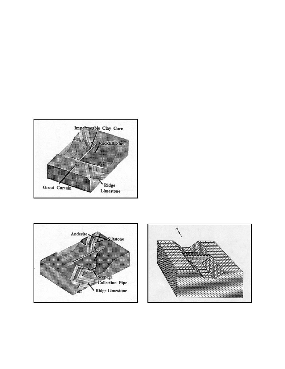
Figure 41. Simplified 3-D model dam, grout curtain,
shown in Figure 44. The output file from the finite
and Ridge Limestone
Figure 42. View showing geology at Cerrillos Dam
Figure 43. 3-D finite element mesh
(rockfill shells are transparent)
A-32

 Previous Page
