ETL 1110-2-563
30 Sep 04
Table C-2
Lognormal Distribution Parameters for Impact Variables at Winfield Upper Approach
Guard Wall
Design Structure
Variable
Mean
Standard Deviation
Minimum
Maximum
θ, deg
Upper approach guard wall
9.3
3.75
0
30
V, ft/sec
1.08
0.7
0
10
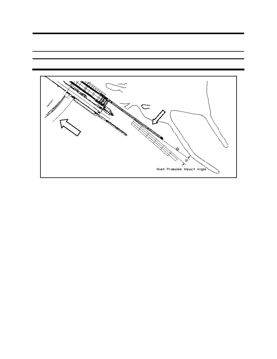
Upper Guide Wall
River Flow
Figure C-12. Upper landside guide wall at Kentucky Locks
(2) Therefore from this design it would be anticipated that the approach angle can be expected to
have a wider degree of variation than was estimated in either the Olmsted or Winfield examples above but
the approach velocities can be expected to be lower. A 1:120-scale navigation model was constructed at
ERDC, but no impact experiments of the upper approach walls were conducted as part of the modeling.
Instead the final design incorporated the use of data from the Olmsted approach walls design since both
designs incorporated floating guide walls. The experiment data from Olmsted was then adjusted based on
the opinions from tow captains that utilize the locks as well as engineering judgment from District
hydraulic and structural engineers. The distributions for impact and forward velocity of the barge are
shown in Figures C-13 and C-14, respectively. The distribution for tow weight was taken from the OMNI
database and is shown in Figure C-15. Table C-3 shows the statistical parameters used for the design of
the upper guide wall.
d. Marmet Upstream Guide Wall, Kanawha River, Marmet, West Virginia (Patev 2000 and Design
Memorandum, Marmet Upstream Guide Wall, Huntington District, 1999).
(1) The Marmet upstream guide wall structure consists of 14 concrete drilled piers spaced at 23 m
(105 ft) center to center and a sheet-pile nose cell, which support 15 precast concrete beams. Figure C-16
shows the layout for the upper approach walls at Marmet. Each pier is constructed of two 2-m- (6-ft-)
diameter drilled shafts with cast-in-place cap beams to support the precast wall beams as shown in
Figure C-17. A thrust block is provided at the cap beam to transfer barge impact from the beam into the
shafts and nose cell. The hollow, rectangular beams have an outside dimension of 3 m by 3 m (10 ft by
10 ft), and the weight of each of the precast beams is approximately 450,000 kg (495 tons).
C-9


 Previous Page
