ETL 1110-2-344
31 Dec 93
gravity body force. There are no gravity body
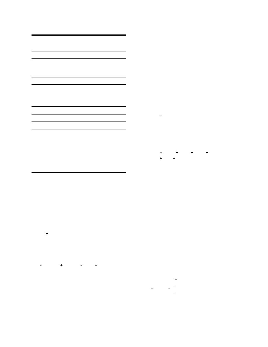
Table A-1
forces applied for the foundation since the deforma-
Material Properties for Locks No. 27
tion due to self weight would have occurred in the
foundation before the construction of the lock.
Body forces in the foundation are ignored by
Concrete
assigning a value of zero to the unit weight of the
Ε
3,500.0 ksi
rock, as shown in Table A-1. The vertical force for
υ
0.2
water in the culvert is omitted because the water
γ
0.150 kip/ft3
level in the lock is below the floor of the culvert.
Rock
Horizontal forces due to hydrostatic and lateral
earth pressures acting on the vertical plane defined
Ε
3,500.0 ksi
by the back face of the monolith and passing
υ
0.2
through the backfill are applied to the mesh as
γ
0.0 kip/ft3
Concrete/Rock Interface
KHγ y
(4)
ph
0.0 ksi .
√in
KIc
Soil
Ε
for y ≤ H and
3.5 ksi
υ
0.35
γ
0.125 kip/ft3
γs
0.130 kip/ft3
KHγH KH(γs
γw)(y
ph
H)
γw
0.0625 kip/ft3
γw(y H)
(5)
ΚH
0.45
KV
0.2
for H < y ≤ (H + Hs), where y is the distance below
the top of the backfill. Figure A-6 illustrates how
where H is the height of the backfill above the
the pressure ph is applied to the mesh. The hori-
zontal force for water in the lock chamber is not
between the water table and the foundation. The
included because the lock is assumed to be
vertical (drag) forces due to differential settlement
dewatered. Uplift pressures are modeled according
within the backfill acting on the vertical plane
to Case 1 of paragraph 3b. Uplift pressures at the
defined by the back face of the monolith and pass-
base of the monolith are applied to the mesh as a
ing through the backfill are applied to the mesh as
combination of pressures and initial stresses. Pres-
sures corresponding to full hydrostatic uplift are
applied on the surface of all elements adjacent to
KVKHγy
(2)
td
the assumed crack surfaces. Initial stresses are
applied to the elements which are adjacent to the
interface between the monolith and the foundation.
The initial stresses σ0 are specified as nodal pore
for y ≤ H and
pressures p and are converted to initial stresses such
that
KVKHγH
KVKH(γs
γw)(y
td
H)
(3)
σxx
p
0
for H < y ≤ (H + Hs), where y is the distance below
σ
p
yy
σ0
(6)
0
σzz
p
Equation 3 is based on the effective pressure. Fig-
0
ure A-5 illustrates how the pressure pv and the trac-
τ
0
xy
tion td are applied to the mesh. The vertical force
0
due to the weight of the monolith is applied as a
A-6


 Previous Page
