
ETL 1110-2-560
30 Jun 01
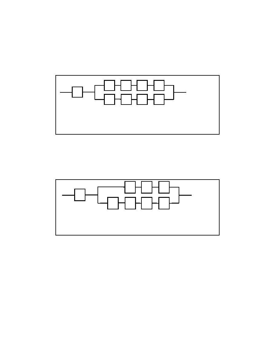
e. Each lock gate (LD1, LD2, LD3, LD4) electrical equipment of Appendix F was extrapolated into
appropriate components as a unique parallel-series block diagram. The diagram is shown in Figure E-5.
The resulting equation is:
RSYS(t) = RM(t) * (1 {1 [RN(t)* RO(t)* RP(t)* RQ(t)]} * {1 [RR(t)* RS(t)* RT(t)* RU(t)]})
(E-4)
N
O
P
Q
M
R
S
T
U
M - Circuit Breaker
R - Fast Speed Forward Starter
N - Slow Speed Starter
S - Fast Speed Reverse Starter
O - Slow Speed Reverse Starter
T - Fast Speed Conductors to Motor
P - Slow Speed Conductors to Motor
U - Motor Fast Speed Windings
Q - Motor Low Speed Windings
Figure E-5. Lock gate (LD) electrical mission reliability block diagram
f. The lock valve (LE1, LE2, LE3, LE4) electrical equipment was similar except the valves do not
have slow speed reverse starter (O) (Figure E-6). The resulting equation is
RSYS(t) = RM(t) * (1 {1 [RN(t)* RP(t)* RQ(t)]} * {1 [RR(t)* RS(t)* RT(t)* RU(t)]})
(E-5)
N
P
Q
M
R
S
T
U
M - Circuit Breaker
R - Fast Speed Forward Starter
N - Slow Speed Starter
S - Fast Speed Reverse Starter
P - Slow Speed Conductors to Motor
T - Fast Speed Conductors to Motor
Q - Motor Low Speed Windings
U - Motor Fast Speed Windings
Figure E-6. Lock valve (LE) electrical mission reliability block diagram
g. The dam gate (DE1 through 14) electrical equipment was similar except the gates do not have
slow speed starters, conductors, or windings (N, O, P, Q) and have parallel redundant circuit breakers (M)
(Figure E-7).
h. The resulting equation is
RSYS(t) = {2*RM(t)-[RM(t)*RM(t)]}*RR(t)*RS(t)*RT(t)* RU(t)
(E-6)
E-3

 Previous Page
