ETL 1110-2-560
30 Jun 01
Appendix E: Electrical Reliability Example
E-1. Description
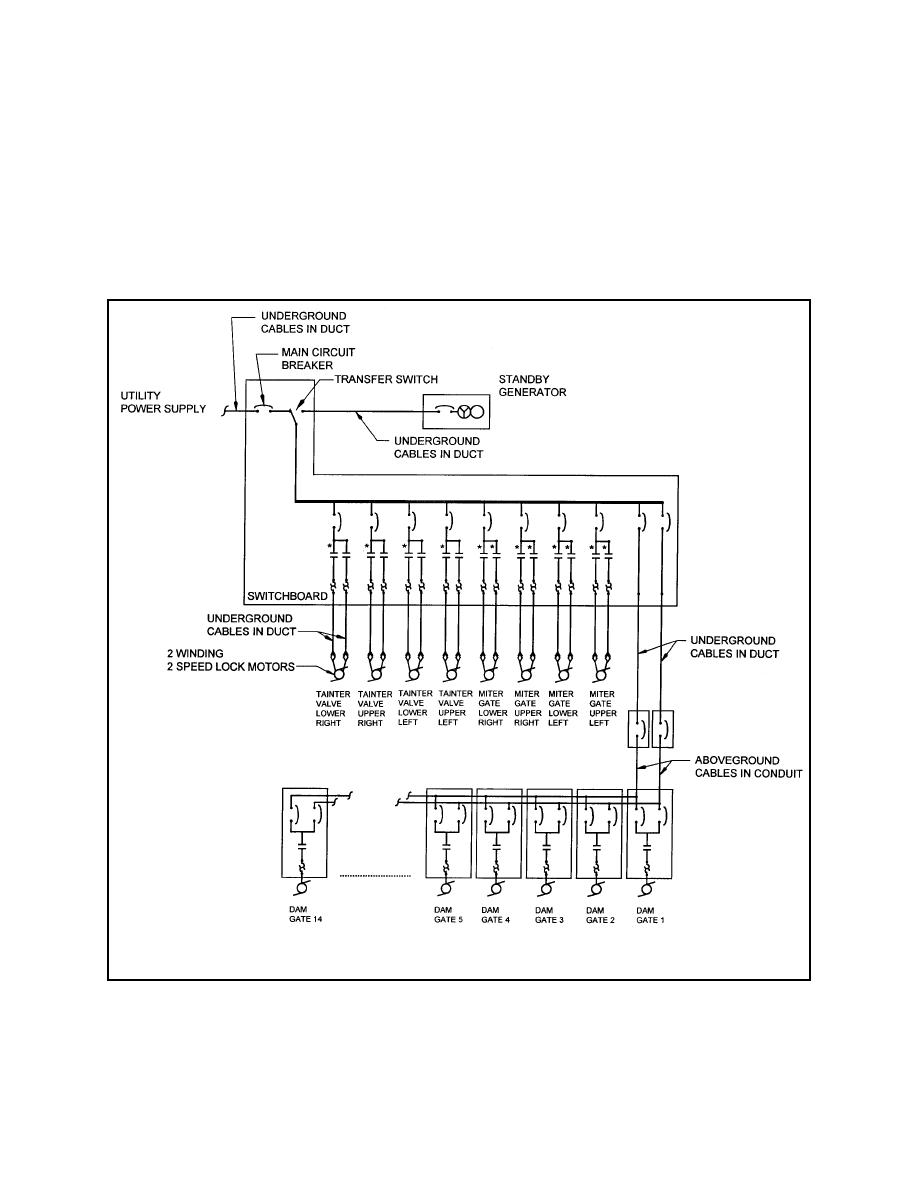
The electrical one-line diagram of the example lock and dam electrical system is shown in Figure E-1.
The mission reliability electrical subsystems were extracted from Appendix F. Several of the electrical
blocks from Appendix F did not have failure rate data readily available. These blocks required further
extrapolation to the extent that available failure rate data were available.
* Forward and Reverse Starters
Figure E-1. Lock and dam electrical one-line diagram
E-1


 Previous Page
