
ETL 1110-2-563
30 Sep 04
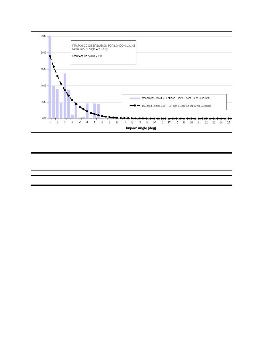
Figure C-21. Probability distribution for impact angle at London Locks upper landside guard wall
Table C-7
Lognormal Distribution Parameters for Impact Variables at London L&D Upper Landside
Guard Wall
Design Structure
Variable
Mean
Standard Deviation
Minimum
Maximum
θ, deg
Upper landside guard wall
2.2
1.5
0
12
V, ft/sec
2.2
0.6
0
10
f. Greenup Locks Approach Walls, Ohio River (Design Memorandum, Greenup Locks Approach
Walls, Huntington District).
(1) As part of the Ohio River Main Stem Systems Study, a preliminary approach wall design was
completed on the extension of the guide and guard walls at Greenup Locks. Currently, the existing
upstream approach conditions are less than desirable due to crosscurrent problems. These crosscurrents
are encountered by tows approaching the lock, which force them to flank toward the bank while their
stern is being pulled toward the river. Figure C-22 shows the flow vectors from the navigation model at
Greenup. In order to ensure an adequate landing zone for the tows, the approach walls will be lengthened
and configured to allow a 366-m (1,200-ft) landing zone for each chamber. In order to facilitate the new
approach to Greenup Locks after the landward existing 183-m (600-ft) lock chamber is extended, the
following approach wall lengths were proposed for the project:
Extend the existing upper river wall and upper middle wall by approximately 410 m (1,345 ft).
Extend the existing lower land wall by approximately 335 m (1,184 ft) beyond the new lower
landside lock monolith causing the wall to project 335 m (1,100 ft) beyond the new lower middle
wall monolith.
Extend the existing lower river wall by approximately 90 m (295 ft). The upper approach walls
are proposed to be floating pontoons, which are restrained laterally by nose piers and pylons.
C-15

 Previous Page
